The Vintage Radio Repair Shop
For all your repair, restoration and servicing needs for Vintage Valve Radio
Telephone 0161 285 1600 Email: info@vintage-
Based in Stockport, Cheshire N.West England but offering Nationwide Service!
Formerly Dab Hand Radio.. Same people, new name! We DO NOT repair DAB Radios!


WELCOME!! If you are seeing this your password worked and you have reached the
Apprentice Zone!
Thank you for your Joining Fee which is to provide some support for the materials I will be sharing with you in the future. I will now have your email and ‘land’ address which is solely so I can contact you directly and, if required, send you items which you might seek or need when repairing a radio. Rest assured I will NEVER divulge your email or address to anyone else. What’s said/done in The Apprentice Zone stays in the Apprentice Zone!
**************************************************************************************************************************************
The Vintage Radio Repair Shop Apprentice DISCLAIMER
For insurance reasons I have to put in here a Disclaimer concerning the nature of our activities which will include working with electrical circuits which have high voltages which can be lethal…. Of course SAFETY is my paramount concern but I do need you to accept that working on old valve/tube radios can be dangerous and I need you to cut and paste this paragraph and return it to me by email as an acknowledgement of the risks involved.
Please digitally sign it and return to me, Name Date
***************************************************************************************************************************************


This Apprentice Zone will soon be populated by information/hints/tips/ but mainly responses to queries and requests made by you, the Apprentice! I hope that this will be the foundation of a long and useful relationship where we can share expertise and learn together. I’m especially looking forward to the discourse I will be having with those of you from The States and the Far East where the radios can be very different to that which can be found in the UK!
More to follow! Keep checking in!

Corona Virus!
Thanks for your understanding!
The Corona Virus is finally passing its Peak here in the UK. We have been supporting our daughter and son as best we can given that they are trying to juggle three under 4 yr old youngsters (daughter 2, son 1) and try and work… Both are self employed so you know the score in terms of help via government etc.. Don't get me started on the way in which here in the UK the pandemic has been dealt with. Suffice to say I’m looking forward to using my vote to get the present bunch of buffoons out of office in due course.
What an awful experience it has been and continues to be and, touch wood, I haven’t been infected. I am working on a couple of videos which with a fair wind and a bit of luck should be on here soon but in the mean time I will be sending each of you (at long last!) the first in a series of Lesson Plans/Information Packs electronically so you can get started. (I may call them something else but its the ‘old teacher’ in me!) These will arrive in the next few days.
I’ll also be pointing you to some of the best You Tube videos to look at. There are a great many on You Tube concerned with restoring and repairing vintage radios and some of them are fantastic but the majority are unsafe and pretty bad! Beware!
I’m planning to have the first … Best wishes all!!
Dave
I don’t get much done with this rascal under my feet!
Meanwhile below are some of my You Tube efforts to take a look at… I’ll improve!

https://www.youtube.com/watch?v=Uw6WOd2cAzQ
https://www.youtube.com/watch?v=_40F5RaR-
https://www.youtube.com/watch?v=wjlVowLUtrM
https://www.youtube.com/watch?v=HgOHHC_rt_M


INTRODUCTION! Hello!
No.1

The Apprentice Files…
Below you will find a series of videos designed to help you start out on your challenge to repair vintage radios!


BACK TO HOME PAGE!
Here’s a problem… Have a think and let me and the rest of the group put forward a few ideas on how this one could be fixed? What’s the problem? What can you see in the photos that might be a cause for concern??
My comments will be in these blue coloured boxes.. Yours in the green! Unfortunately you won’t be able to comment directly into the green boxes but email me and I’ll publish your comments…
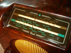
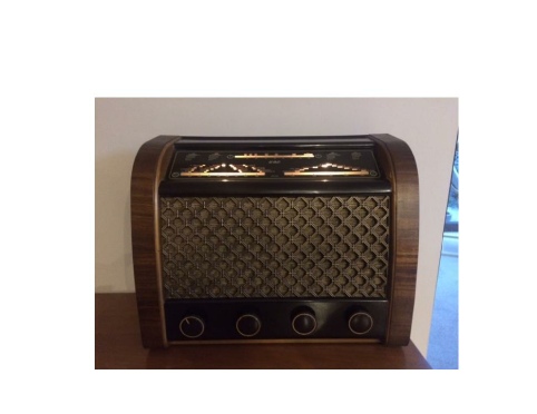
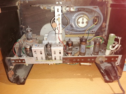
Someone has asked me to take a look at a Steepletone radio/CD player that they have that holds great sentimental value for them. It was being used and then “just stopped working”. I’ve discovered a slow blow 2A fuse inside. This had failed and there is evidence of heating on the corner of the circuit board that is fed by the current after the fuse. I replaced the fuse and, unsurprisingly, it blew too. Would you have any idea what is causing the problem and is it an easy fix?

Done some more checks and discovered that one of the diodes that firm the rectifier has had it! Other three show forward voltage of 0.55V and it shows basically nothing.
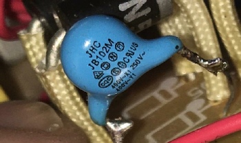
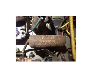
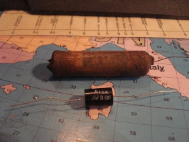
This is the capacitor:
As you said, mains-
What would be the likely purpose of this capacitor? Is it a possible source of my problems? (Some hum as soon as powered up and then internal slow blow fuse blows within seconds of power up). If not, please could you suggest where I might go next. I can see how I could check the AC in from the transformer but am now sure after that.

An update on the CD/radio that I was working on. It is fixed! In the bridge rectifier each diode had a capacitor in parallel. One of these was the odd blue one. One of the others tested short circuit. This gave the impression that the diode in parallel with it had failed. I replaced the blue cap and the shorted one and all is now well. I assume that, when the diode was supposed to be reverse biased, the capacitor was allowing current to flow.

MEMBERS PROBLEMS…..

A stumbled Steepletone from Shaun….


So, what do we think folks??
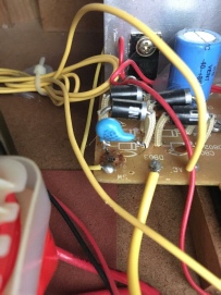
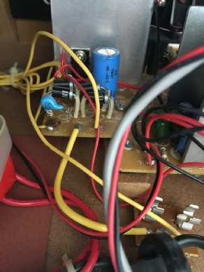
This capacitor has obviously been changed in the past.. Its a 0.001uf high voltage type (the 102 on the side points to its value)


The plot thickens! I replaced the diode that appeared to be the problem and the new one shows the same issue! Basically it tests for continuity in both directions! The “faulty” one that I took out tests fine now that it isn’t in the circuit.
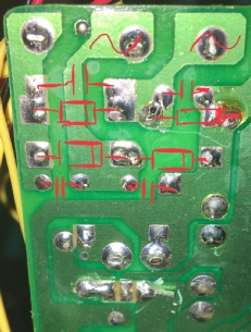
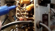
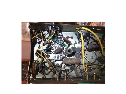
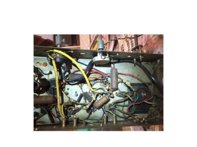
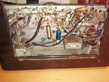
Here’s a photo of the underside of the board with some components marked on. The diode in question is at the top right. Each diode has a capacitor across it. The mains rated capacitor is across the diode top left.

A capacitor connected across the output allows the AC signal to pass through it and blocks the DC signal, thus acting as a high pass filter. The output across the capacitor is thus an unregulated filtered DC signal. This output can be used to drive electrical components like relays, motors, etc.
Can you test a diode in circuit?
A diode is best tested by measuring the voltage drop across the diode when it is forward-

It's certainly a good indication that there was a problem with that component and that someone has had a go at it. The problem is trying to sort out what the value of the capacitor is (a good bet would be 0.1uf…. we later discovered it was a 0.001uf) but mains rated ie high voltage, as it looks like the full 240mains voltage goes across it?
What's the capacitor to its right(as you look at the photo)?? It could be the same...

RESULT! Not that I helped that much!

VIDEO!
******************************************************************************************

START HERE!

MEMBERS PROBLEMS…..

Hey Dave,
Hope you are well
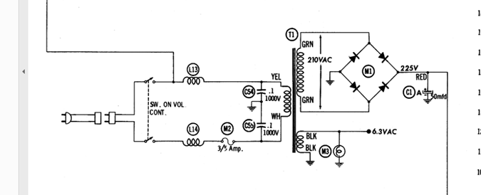
I have a question about safety caps. I am working on a Telefunken Jubilee. In the schematic below, would I replace C54 and C55 with Y2 safety Capacitors? I could really use some lessons in how and when to use safety capacitors. Thanks Ken
Thanks for your message and I'm glad you asked... I've cut and pasted the info below which should help.
In the circuit you have C54 and C55 should technically be Y class as they are directly grounded rather than straight across the mains and 'floating' so to speak, which is what the X class do..
In your Telefunken it really wouldn't matter whether you used an X or Y capacitor as long as their rating and voltage are ample for the high volts they would absorb. Having said that I have some here which are only rated to 630 volts but they work fine. I'm saying that because in the Telefunken we are not talking massive industrial type voltages so a basic high rated 0.1uf would be fine in each case...So just remember not to touch the wires with your bare hands on power up. Class-
Class-
In order for these capacitors to perform their EMI/RFI filtering tasks, they are directly connected to the AC power input, that is, the AC “line” and the AC “neutral” . And because of this direct connection to the AC voltage, the capacitors may be subjected to overvoltages and/or voltage transients—lightning strikes, power surges. Thus, capacitor failure is a very real possibility.
When a Class-
If a Class-
Applications for Class-
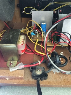
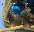
Familiar photo? (Shaun!)
Subclass X2 and Y2 are the most commonly used safety-
Whereas X2 and Y2 caps are appropriate for household applications, X1 and Y1 safety capacitors are used in industrial settings. As an example, a subclass X1 safety capacitor would be used for an industrial lighting ballast that is connected to a 3-
Of course, you could always use subclass X1 and Y1 in non-
You might be asking, are X2 and Y2 safety capacitors interchangeable?
A Y2 capacitor can safely be used in place of an X2 capacitor, but an X2 capacitor should not be used in place of a Y2 capacitor. This is because, although an X2-
There are also safety caps that combine aspects of X and Y types, such that they have met both X and Y safety requirements and standards. So for an X1/Y1 combination, this simply means that the capacitor can be used either as an X1 capacitor in a line-
Hope that helps and keep the questions coming... That's the best way of learning.
Dave


From Ken…
Here's the problem I am having with this Telefunken. I replaced the filter caps yesterday (actually re-
Got any ideas?


I think you may have nudged something on the earthing side when you replaced the wire? Check and test all your earth points for dry joints and also look at the routing of the new wire.. Has it followed exactly the same course as the original? Check that any circuit boards are all earthed together etc.
Check that the new caps haven't dry joints and also check any tracking on the boards (if that's appropriate)
I'm not familiar with that radio but I'll go and have a look at the circuits on the net and get back to you
Chin up it will be sorted!
You were right, it was the negative lead of the filter cap, bad solder point. Fixed and working great now. Thanks!

RESULT! Well done Ken!
*********************************************************************************************
VIDEO!

TWO videos for you! I’m not brilliant at these but will hopefully get better.
Check out this YouTube Video recommendation too!
Subscribe! https://www.youtube.com/c/dlab500/videos
The Power Limiter!
Marking the spots!
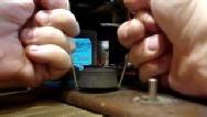
Getting those Knobs off!!


https://www.youtube.com/watch?v=cJzRcJJIIs8
https://www.youtube.com/watch?v=b6k-

REMEMBER… Always have in mind SAFETY and be METHODICAL!

Videos for your perusal….
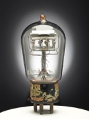
All about valves…..
https://www.youtube.com/watch?v=nA_tgIygvNo&list=RDnA_tgIygvNo&start_radio=1&t=63
https://www.youtube.com/watch?v=5WCWejeRR_s
https://www.youtube.com/watch?v=oHjZs0bNwEs

https://www.youtube.com/watch?v=oqV2xU1fee8
Follow this link for tips on soldering!

https://www.ebay.co.uk/itm/Series-

This Unit is cheaper to buy than make yourself!


March 2021… Members Stories.
We recently did a bit of a service on Philip’s GEC , Below are the photos taking a chronological journey on the process. I supplied the capacitors and we ‘met’ via WhatsApp video to discuss how to do it!
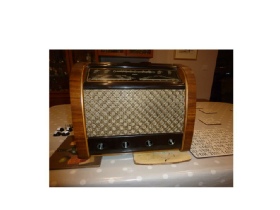
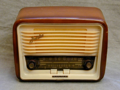
The start a venerable GEC5445
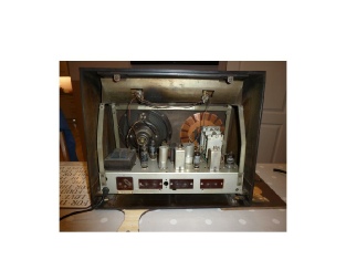
Back off.. Find an old margarine tub to put all
the screws in..Don’t lose them!
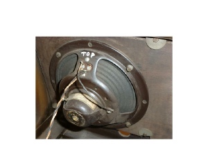
Phil wasn’t sure about the loudspeaker
as it sounded ‘off’. A new one was bought,
Sourced from a cheaper but good car spares speaker 4ohms!
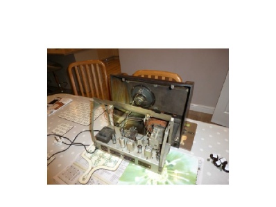
The kitchen table workshop… Cleaning, if required, via vacuum cleaner and soft paint brush.
Below.. The nitty gritty. Those old paper capacitors must go! One at a time… Repalce one, test.. Replace another, test….Mark each soldering point! If the phone rings…. You WILL forget where the soldering points were…
Mark, replace, test, one by one…

Modern replacement capacitors are much smaller than the old..but much better!
FINISHED! With new dial bulbs too!

If you haven’t already make sure you have sent your mobile phone number to me so I can include you in the WhatsApp group.. Its proving to be the easiest way, and free, to communicate ‘live’ via video and I can talk you through your project…

Next up! Richard’s Ekco U319.. I’ve sent Richard a packet of capacitors and other bits and bobs ready to tackle the service on this set. The first issue we have to explore is whether or not the radio works! He’s not plugged it in yet and is currently making his power limiter. I must stress that first inspection to determine what is or isn’t wrong with a radio is essential. To just go ‘gung ho’ and change all the dodgy looking capacitors without really knowing where a fault is, if there is one, is a recipe for disaster….

Coming Soon! The dial light improvement for Bush DAC90A’s……